Planning a home network: outlets, patch panel and Wi-Fi in one example
A small flat to try out: where the network cables run, what happens in the network cabinet, and how walls and band change the Wi-Fi.
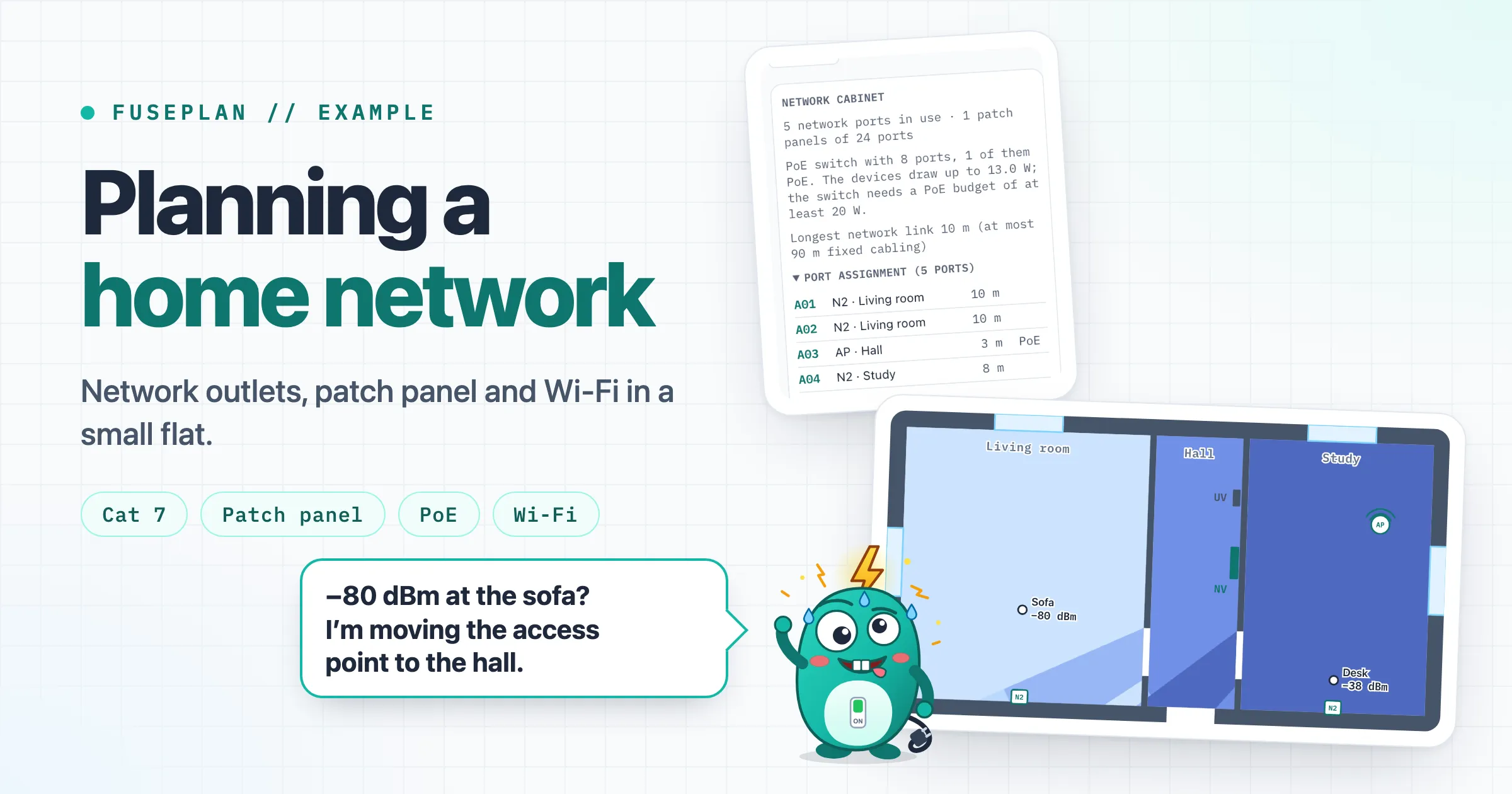
The example is a flat with a living room, a hall and a study, about 9.7 × 5 m. The network cabinet hangs in the hall; the living room and the study each have a double network outlet, and an access point on the hall ceiling provides the Wi-Fi. The room planner calculated the cable routes, ports and Wi-Fi maps in the demo.
Every outlet gets its own cable
Network cables run in a star. Each outlet has a cable of its own all the way to the network cabinet, with no branch on the way. A double outlet gets two cables. In the cabinet, every cable ends on a port of the patch panel. Port and outlet carry the same label, A01 to A05 in the example.
A short patch cable runs from the patch panel to the switch. The switch connects all ports with each other, including the router, which brings the internet into the network. The room planner counts the ports in use: five in the example, plus one for the router. With 20 % reserve that makes a switch with 8 ports.
The access point gets its power over the network cable (PoE, Power over Ethernet), so it needs no socket on the ceiling. The room planner assumes 13 W for it and, with the loss in the cable, arrives at a switch with a 20 W PoE budget. The network cabinet itself gets a circuit of its own, a B16 in the example, so router and switch don’t go down with another appliance.
Tap an outlet to see its cable and the port it ends on in the network cabinet.
Move the access point and switch band and walls. The map shows the estimated signal one metre above the floor.
Access point
Band
Inner walls
Wi-Fi: walls, band and where the access point hangs
The room planner estimates Wi-Fi with the multi-wall model from COST 231. It takes the free-space loss on the direct line from the access point and adds a fixed value for every wall on the way. For masonry inner walls that is 6 dB at 2.4 GHz and 10 dB at 5 GHz, for concrete 12 and 18 dB, for drywall 3 and 4 dB. These are round assumptions, not measurements.
The room planner’s guide value for living spaces is −67 dBm, enough for video calls and streaming. With the access point on the hall ceiling, the whole flat is at that guide value or above in all six combinations of band and walls. At 5 GHz with masonry, −48 dBm reach the sofa and −49 dBm the desk.
Now move the access point into the study in the demo and set the inner walls to concrete. At 5 GHz the signal at the sofa drops to −80 dBm, where things get slow and the connection may drop out. Only 54 % of the area is still at its guide value or above. At 2.4 GHz the sofa gets −61 dBm, because 2.4 GHz loses less at every wall and over the distance.
The map in the demo splits the room planner’s top step (−67 dBm and stronger) again at −50 and −60 dBm, so the walls show in a flat this small. In the room planner that range is one colour.
In the room planner
In the Network tab of the room planner you place the network cabinet, network outlets and access points. The network cabinet’s panel shows the ports in use, the switch size, the PoE budget and the port assignment with the labels for outlet and patch panel. The ports follow the order of the outlets in the plan and move up when an outlet is added, so label them once the plan is final.
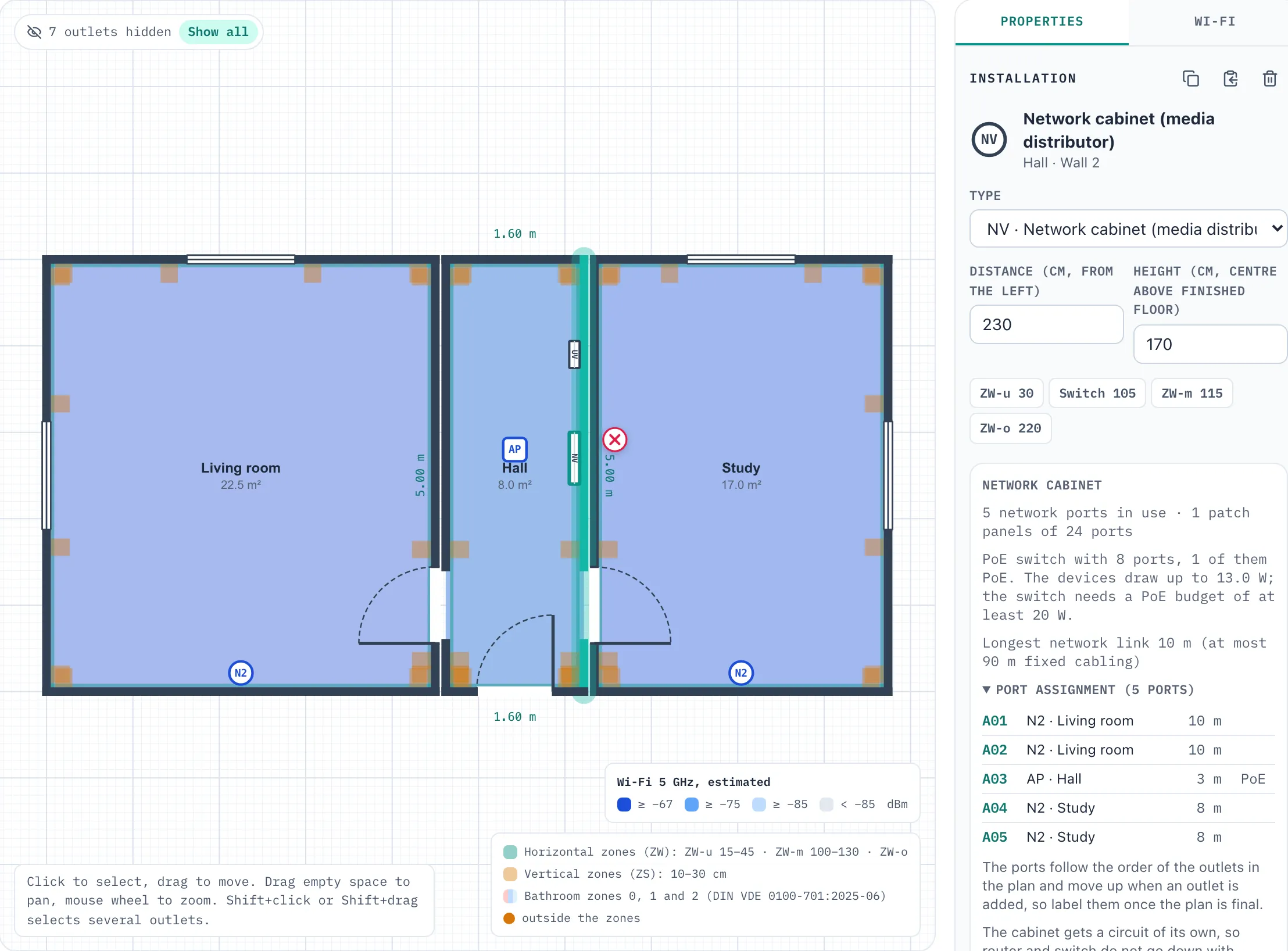
The network cabinet in the example: 5 ports in use, a PoE switch with 8 ports and the port assignment with the length of each cable.
The Wi-Fi layer shows the map for 2.4 or 5 GHz, and you set the construction of inner walls, outer walls, floors and windows. “Suggest access points” adds them on the ceiling one at a time, until 95 % of the area reaches its guide value or one more would add less than 3 %. A network link longer than 90 m shows up in the Hints tab.
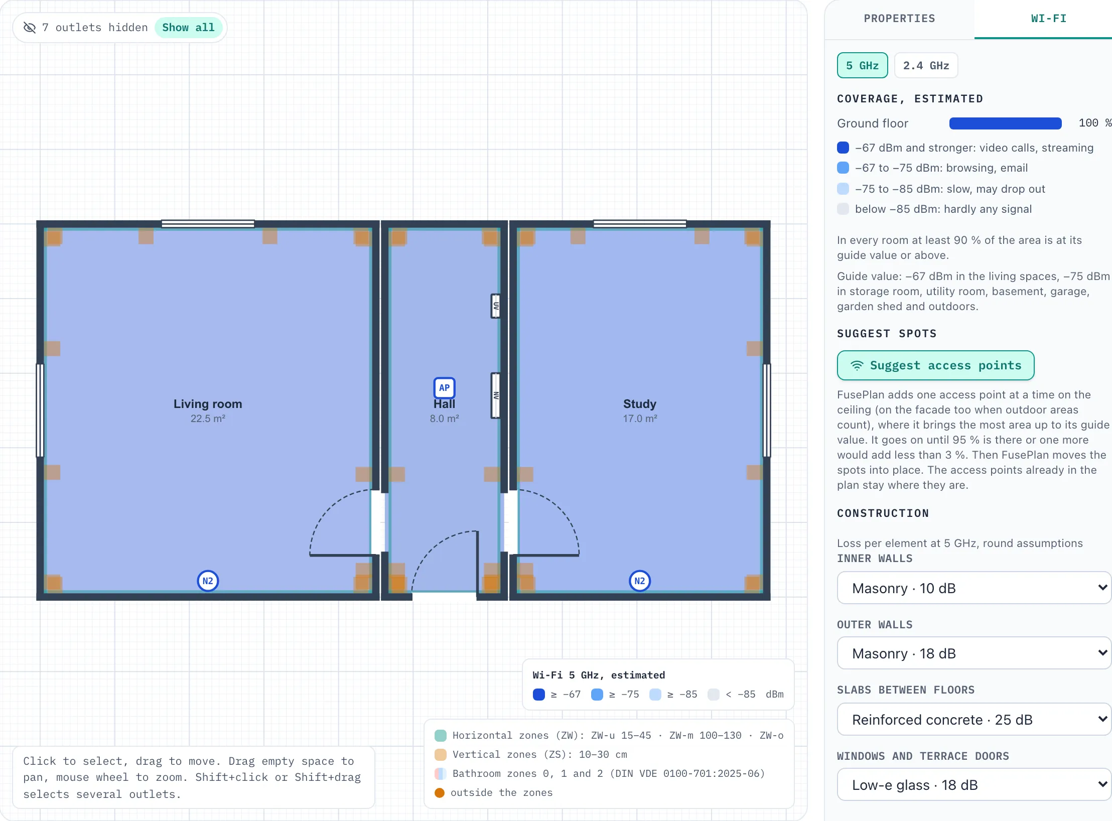
In the room planner, at 5 GHz with masonry, the whole flat gets −67 dBm or stronger. On the right you set band and construction.
The link under the demo opens the example in the room planner.
Comments
Write a comment